Die foundry
Design of supply for molds
In high pressure die casting, metal is put in a compression room (container or "gosseneck") and is pushed by a piston (like a syringe) in channels to the entrance of pieces (attack) To finally fill the imprint of the piece.
The three phases of high pressure die casting :
Phase 1 : Metal is slowly brought to the edge of eache pieces (time between 1 and 4 secondes)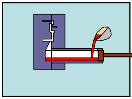
Phase 2 : Metal is fastly injected and fills the cavity of the piece and des talons de lavage(?) (time betweeb 10 and 200 ms)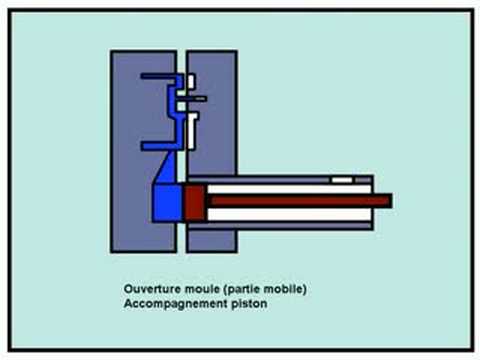
Phase 3 : Metal is compressed with high pressure (pressure between 400 and 1000 bar)
Path of reasoning design of the power supply design system.
We start with the characteristics of the piece.
1) The volume of the piece alone that must be made to which is added the volume of the heels of washing which will allow a good health of the room and the exit of the air (vents) that is in the mold before the arrival of the metal.
2) The minimum thickness of the part that defines the filling time which is all the shorter as the part is fine. For example, the filling time of a piece with a minimum thickness of 2 mm is between 20 and 60 ms.
3) Depending on the type of attack with or without change of direction at the time of penetration into the cavity, we will have an estimate of the speed of the metal on attack (Which is of the order of 40 ms, that to say 144 km / h).
4)The volume to be injected, the filling time, and the speed of attack make it possible to calculate the attack section (Its surface of the entrance door that the metal will use to fill the shape of the piece).
5) The power supplies are drawn between the attacks of each cavity (multi-cavity mold) to a single arm which is connected to the compression chamber. The changes in the direction of the trajectories are minimized in order to limit the cavitation phenomena by respecting the rule of the cumulative sections at each arm unification (the overpressure must be guaranteed).
6) It is now possible to calculate the weight of the complete cluster and verify that the calculated piston speed is compatible with the characteristics of the machine.
7) The diameter of the piston is chosen with the degree of filling of the metal in the container. The volume of air that is trapped in the compression chamber with the metal is deduced therefrom.
8) We thus know the total volume of air (container + food + parts + washing heels) that will have to be evacuated in order not to find this air trapped in porosities under pressure in the room (smoker's humor because there are always Porosities in a pressure chamber). Thus, the surface area of the openings of the air drawings is calculated for a mold without a vacuum system with an air leakage rate of 200 m / s.
9) When this is necessary a computer simulation filling will verify that the metal is at the door of each piece at the same time.
10)Once the power supply is validated, the volume of molten metal injected gives us the amount of heat to be removed by the thermoregulation system and other techniques.